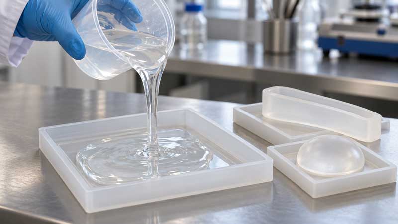
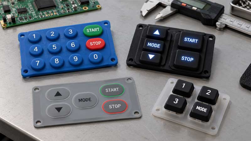
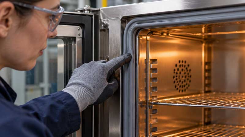
Silicone keypads are usually produced using compression molding, the dominant process in the industry. First, the raw silicone compound is shaped in a heated steel mold under high pressure. Then, it is cured, finished, and tested before shipment. The following information is intended to help you understand the underlying structure, design, parameters, and other aspects of production.
If you want to see how silicone keypads are produced, explore our Silicone Keypad Manufacturing Videos for insights into the production process.
What Is a Silicone Keypad and How Does It Work?
The Basic Structure
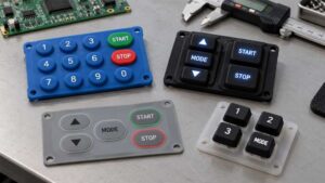
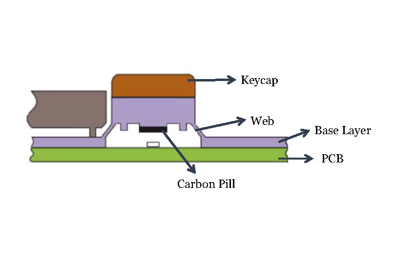
A silicone keypad is not made up of individual keys. Rather, it is a single molded piece of silicone rubber referred to as a continuous sheet. Sometimes it is called a “keymat” or “elastomeric keypad.”
That one piece does multiple jobs simultaneously:
- The keycaps — the raised buttons users press
- The web — thin silicone walls connecting keycaps to the base, acting as a spring
- The base layer — the flat perimeter that seals against the device housing
- The conductive contact — a small carbon or gold pill molded into the underside of each keycap
Because there are no seams or gaps between components, the keypad naturally resists dust, moisture, and contamination. Many silicone keypads achieve IP67 or IP68 ratings without any additional gasketing.
How a Key Press Becomes an Electrical Signal
The mechanism is simple. That simplicity is the point — fewer parts means fewer failure modes.
Here is the complete signal chain:
- Press — A finger applies downward force to the keycap. The silicone web begins to deform.
- Buckle — At a certain compression depth, the web snaps inward suddenly. This is the tactile click. It is not mechanical. It is elastic geometry.
- Contact — The carbon pill (or gold contact) on the underside of the keycap touches the PCB trace below. The circuit closes.
- Signal — An electrical signal travels through the PCB to the device’s processor. The keypress is registered.
- Release — The user lifts their finger. The silicone’s elastic memory instantly restores the web to its original shape. The circuit opens. The key is ready for the next press.
Because this mechanism contains very few moving parts, silicone keypads typically achieve much longer lifetimes than mechanical switches.
The Silicone Keypad Manufacturing Process: 8 Steps Explained
Step 1: Product Design and Engineering
At the design stage, engineers define:
- Key layout and geometry — number of keys, spacing, key shape (flat, domed, conical)
- Key travel distance — how far a key moves before triggering. The industry standard optimum is approximately 1.5 mm (0.060 inches)
- Actuation force — how much pressure is needed to trigger each key. Ranges from 20 g for feather-touch medical interfaces to 500 g for gloved-hand industrial panels
- Backlighting—whether keys need to transmit light and which backlight logic applies: legend-transmissive (the legend itself glows, requiring laser etching and a translucent silicone base), legend-blocking (the surround glows, and legends are printed in opaque ink), or no backlight at all. This choice must be locked in before mold fabrication—it determines both the base material and the finishing process.
- Sealing requirements — IP rating targets that will influence base flange geometry and wall draft angles
The single most important design parameter is the snap ratio.
The snap ratio is the relationship between a dome’s height and its wall thickness. A high snap ratio produces a sharp, crisp tactile click. A low snap ratio creates a soft, linear response with almost no click sensation. The appropriate snap ratio depends entirely on the application.
For instance, a keypad for a cardiac monitor requires soft, silent actuation, so it needs a low snap ratio. Conversely, a keypad for an outdoor industrial controller requires unmistakable feedback, even when the user is wearing work gloves, so it needs a high snap ratio.
Step 2: Mold Design and Fabrication (CNC + EDM)
A standard silicone keypad compression mold has two plates:
- Top plate (cavity) — forms the external surface of the keycap, including texture and logo geometry
- Bottom plate (core) — forms the internal web geometry and the pocket that holds the conductive carbon pill
Both plates are machined from steel, most commonly P20 (for medium-volume tooling) or H13 (for high-volume hardened tooling). Prototype molds may use 7075 aluminum to reduce lead time and cost.
CNC milling removes the bulk of material. Tolerances are typically held to ±0.05 mm.
EDM (Electrical Discharge Machining) follows. Electrical discharge machining (EDM) uses controlled electrical sparks to erode metal, creating sharp corners and fine dome geometry that cannot be reached by rotating CNC cutters. The dome profile, which governs snap ratio, is almost always finished with EDM.
After machining, mold surfaces are polished or textured to achieve the target surface finish on the molded part. A matte mold surface produces a matte keypad. A polished surface produces a glossy one.
Mold trial shots follow. First-off parts are measured against engineering drawings. Adjustments are made. This cycle repeats until dimensional and functional specifications are confirmed.
| Mold Material | Hardness | Typical Lifespan | Best For |
|---|---|---|---|
| Aluminum 7075 | Soft | 5,000–10,000 shots | Prototypes, design validation |
| P20 Pre-hardened Steel | 28–34 HRC | 300,000–500,000 shots | Medium-volume production |
| H13 Hardened Steel | 48–52 HRC | 1,000,000+ shots | High-volume production |
Step 3: Raw Material Selection and Preparation
There are two primary silicone types used in keypad manufacturing:
| Property | HCR (High Consistency Rubber) | LSR (Liquid Silicone Rubber) |
|---|---|---|
| Physical state | Dough-like, solid putty | Gel-like, flows freely |
| Curing agent | Peroxide catalyst | Platinum catalyst |
| Molding process | Compression molding | Liquid injection molding (LIM) |
| Typical Shore A range | 40–80 | 20–80 |
| Max temperature resistance | ~200°C | ~250°C |
| Flash formation | Moderate — requires trimming | Minimal |
| Tooling cost | Lower | Higher |
| Best suited for | Most industrial and consumer keypads | Medical, automotive, ultra-precision |
HCR is the workhorse of the industry. It is cost-effective, well-understood, and compatible with a wide range of pigments and additives.
The compound is mixed on a two-roll mill with:
- Pigments — matched to Pantone or RAL color references
- Reinforcing fillers — fumed silica to increase tear strength and abrasion resistance
- Curing agent — peroxide ratios calibrated to target Shore A hardness (typically 50–70 for consumer/industrial keypads)
- Conductive additives — for carbon pill formulation
Step 4: Silicone Preform Preparation
Before closing the mold, operators prepare preforms, which are hand-weighed and hand-cut slugs of silicone compound sized to exactly fill each mold cavity.
The preform process:
- Weigh silicone material.
- Cut the silicone into preform shapes.
- Place the preform into the mold cavity.
Accurate preform preparation helps ensure the following:
- consistent molding pressure
- uniform key geometry
- minimal material waste
Step 5: Compression Molding — The Core Process
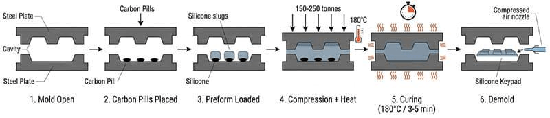
- Preheat the mold — electric heaters bring the mold to operating temperature (170–200°C). Temperature uniformity across the mold face is critical. Hot spots cause variable cure rates and dimensional inconsistency.
- Place carbon pills—conductive carbon pills are placed into their designated pockets in the mold base. They will bond to the keypad body during cure.
- Load preforms — silicone preforms are placed into each cavity. For multicolor keypads, different colored preforms are positioned precisely according to key assignment.
- Close the mold — the press applies clamping force. Standard range: 150–250 tonnes, depending on mold platen area.
- Hold for cure—the silicone heats, flows, fills all cavity features, and cross-links. Standard cure cycle: 180°C for 3–5 minutes. The exact duration is calculated from the thickest section of the part.
- Open and demold—the press opens. Operators use pressurized air guns to assist part removal. Parts exit the mold at approximately 60–80°C and require heat-resistant gloves to handle.
Step 6: Curing, Demolding, and Flash Removal
Vulcanization does not always occur fully during the primary molding cycle, particularly in thick-walled sections. Post-curing addresses this issue.
Post-cure involves placing demolded parts in a ventilated oven at 180–200°C for 2–4 hours. This step:
- Drives off residual peroxide byproducts (which cause odor and can affect skin safety ratings)
- Completes cross-linking in thick sections
- Stabilizes dimensions — reduces post-mold shrinkage variation
- Is mandatory for food-contact, medical, and any FDA/CE-regulated application
After the primary cure, a flash forms on every part. Flash is thin webs of excess silicone that escaped the mold parting line. This flash must be removed before any further processing.
Flash removal methods:
- Die-cut trimming — a matched cutting tool punches around the part outline. Fast and consistent for high-volume runs.
- Manual trimming — operators use scissors or knives. Used for complex shapes or low volumes.
- Cryogenic deflashing — parts are frozen with liquid nitrogen, making flash brittle, then tumbled to snap it off cleanly. Used for ultra-clean medical parts.
Step 7: Conductive Element Integration
A silicone keypad without conductive contacts is just a rubber mat. This step is what makes it an electronic component.
Silicone rubber itself is an insulator. To complete a circuit when a key is pressed, each keycap needs a conductive element on its underside that can bridge the gap between two PCB traces.
There are three main approaches:
| Technology | How It Works | Advantages | Limitations | Best Application |
|---|---|---|---|---|
| Carbon pills (co-molded) | Conductive carbon-silicone compound molded directly into the keycap base | Permanent bond, lowest cost, IP-compatible, proven at 3M+ actuations | Contact resistance can increase with extreme wear (>5M cycles in harsh environments) | Consumer electronics, industrial panels, remotes |
| Conductive ink printing | Silver or carbon ink screen-printed onto the cured keypad’s underside | Thin profile, compatible with flexible circuit integration | Less durable than co-molded carbon; ink can delaminate | Thin keypads, hybrid membrane-silicone designs |
| Metal domes | Stainless steel snap domes placed beneath the silicone key, separately from the keypad | Very precise, crisp tactile feedback; extremely low contact resistance | More assembly steps; higher cost | ATM keypads, industrial controls requiring positive feedback confirmation |
Carbon pills are the right answer for 90% of projects. They are reliable, cost-effective, and eliminate an assembly step by being part of the keypad itself.
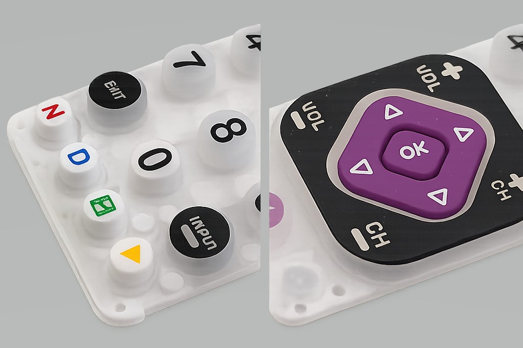
Step 8: Surface Finishing and Legend Application
The molded keypad body is technically complete after Step 7. But it looks like a plain rubber mat. This step gives it identity — the legends, colors, textures, and coatings that make it a finished product.
For realizing the backlighting effect for silicone keypads, laser etching is an effective printing technique, and more information about the difference between screen printing and laser etching is explained in SKF.
Legend application methods:
| Method | Process Summary | Durability | Cost Level | Best For |
|---|---|---|---|---|
| Screen printing | Silicone ink pushed through a mesh screen onto the key surface; oven-cured. One screen per color. | Good with topcoat (100k+ rub strokes) | Low | High-volume consumer products, multi-color designs |
| Laser etching | Laser removes surface paint to reveal backlit silicone beneath. No ink used. | Excellent — permanent, no peeling | Medium | Backlit keypads, premium industrial products |
| Two-shot (co-injection) molding | Two silicone colors molded sequentially; legends are integral to the part | Permanent — cannot wear or peel | High | Medical, military, zero-maintenance applications |
| Pad printing | Ink transferred via a soft silicone pad; handles curved surfaces well | Moderate | Low–Medium | Complex 3D shapes, small runs |
Protective coatings — the layer that protects everything else:
All printed keypads rely on a topcoat. The type of coating matters more than most buyers realize. More information about protective coating options and protective coated silicone keypads can be found in SKF.
- PU (Polyurethane) coating: The most common choice. It is available in smooth, matte, or semi-matte finishes. Resistant to oils and mild chemicals. It adds 0.05–0.15 mm to part thickness.
- Epoxy coating: Harder, glossier surface. It has better scratch resistance. It is less flexible than polyurethane (PU) and is not recommended for highly curved surfaces.
- Parylene coating: Super-thin, conformal coating (2–25 μm) applied via vapor deposition. It is exceptional for medical devices and electronics in extreme environments. Higher cost and longer lead time.
- Matte/soft-touch coating: Minimizes fingerprints. It provides a premium tactile feel. It is common in consumer electronics and high-end industrial interfaces.
Compression Molding vs. Liquid Injection Molding
| Feature | Compression Molding | Liquid Injection Molding (LIM) |
|---|---|---|
| Silicone type | HCR (solid, dough-like) | LSR (liquid, gel-like) |
| Curing agent | Peroxide | Platinum |
| Mold cost | Lower | Significantly higher |
| Cycle time | 3–5 minutes | 30–60 seconds |
| Flash formation | Moderate — requires trimming | Minimal — near-zero flash |
| Dimensional precision | High | Very high |
| Automation level | Semi-automated | Highly automated |
| Minimum order quantity | Lower | Higher (to justify tooling) |
| Best for | Most industrial and consumer keypads | Medical devices, automotive, ultra-high volumes |
The practical decision rule:
- If your annual volume is under 500,000 units and your design doesn’t involve medical-grade cleanliness requirements. Choose compression molding.
- If you need zero flash, ultra-tight tolerances, or Class VI biocompatibility. Choose LIM.
Compression molding remains the right choice for the vast majority of silicone keypad projects. It is a mature, proven, cost-optimal process for the mechanical and electrical demands of keypads.
If you are considering the transfer molding or overmolding technique for your silicone keypad project, more information can be found in SKF.
Key Design Parameters That Affect Silicone Keypad Performance
Three technical parameters define how the keypad will actually perform in use.
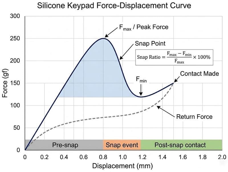
Snap Ratio
Snap ratio is the ratio of the maximum force required to depress a key to the minimum (return) force during the snap event. Expressed as a percentage.
Snap ratio (%) = [(F_max − F_min) / F_max] × 100
- High snap ratio (>50%) — The key clicks sharply, like a ballpoint pen. The user receives unmistakable tactile confirmation. This is ideal for industrial panels, remote controls, and other devices operated without visual feedback.
- Low snap ratio (<30%) — The key presses smoothly with little to no click. This is preferred for medical monitoring equipment, touchpad overlays, and high-precision instruments where preventing accidental actuation matters more than providing feedback.
- Moderate snap ratio (30–50%) — The broadest range. It is suitable for consumer electronics, automotive controls, and most commercial applications.
What controls snap ratio?
- Dome height (taller = higher snap ratio)
- Web wall thickness (thinner = higher snap ratio)
- Web wall angle (steeper = higher snap ratio)
- Silicone hardness (softer = lower effective snap ratio at a given geometry)
Shore A Hardness
Shore A is the standard hardness scale for flexible rubber materials. On the Shore A scale:
- 0 = no resistance (liquid-like)
- 100 = maximum hardness (rigid rubber)
For silicone keypads, the practical range is Shore A 30–80.
| Shore A Range | Feel | Typical Application |
|---|---|---|
| 20–35 | Extremely soft, gel-like | Medical wearables, skin-contact interfaces, baby products |
| 40–50 | Soft, compliant | Medical device panels, food-service equipment |
| 50–65 | Medium — the “standard” keypad feel | Consumer electronics, remotes, calculators, most industrial panels |
| 65–75 | Firm, positive resistance | Heavy industrial controls, military equipment |
| 75–80 | Hard rubber feel | Structural keypads, high-force industrial applications |
Hardness affects more than feel. Softer silicone is more susceptible to surface marking and wear from printing. While harder silicone resists surface damage better, it requires a higher actuation force, which can cause fatigue in users performing high-repetition tasks.
Actuation Force
Actuation force is what the user experiences as “how hard is it to press this button.” It is measured in grams-force (gf) at the nominal key travel distance.
| Key Profile | Actuation Force Range | Notes |
|---|---|---|
| Flat key | 20–100 gf | Low dome height, minimal snap ratio |
| Standard dome key | 100–250 gf | Most common profile. Balanced feel. |
| Conical/tall dome key | 150–400 gf | High snap ratio. Strong tactile click. |
| Industrial panel key (glove-operated) | 300–500 gf | Prevents accidental actuation |
| Medical/soft-touch key | 20–80 gf | Minimum user effort, quiet actuation |
Optimal key travel: 1.5 mm (0.060 inches). This is the depth at which most users receive the clearest tactile feedback without requiring excessive key depression.
Actuation force is not a fixed property of silicone. It is the result of the interaction between dome geometry, Shore A hardness, and snap ratio. Changing any one of these variables changes the force curve.
Quality Control in Silicone Keypad Manufacturing
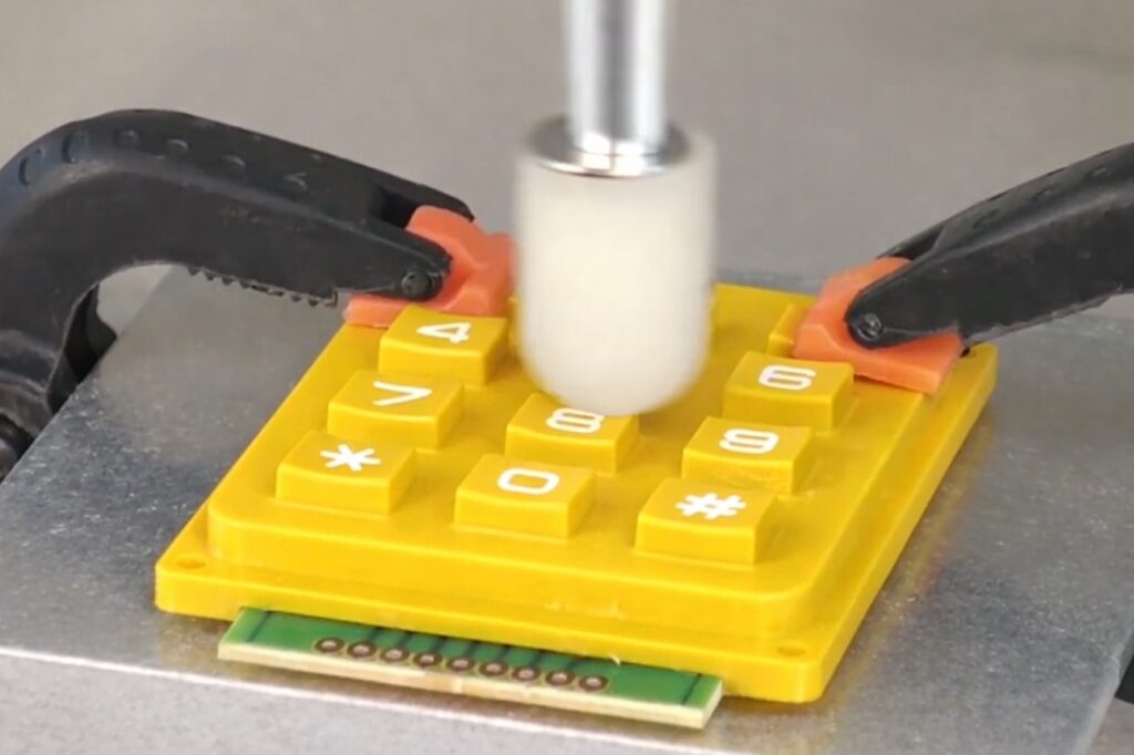
Quality control is not a final inspection step. At SKF, it is embedded into every production stage.
| Test | Method | Pass Criteria |
|---|---|---|
| Actuation force | Universal testing machine, calibrated load cell | Within ±15% of specified force |
| Key travel (stroke) | Contact displacement measurement during actuation | Within ±0.1 mm of target |
| Contact resistance | 4-wire Kelvin measurement at rated actuation force | < 500 Ω initial; < 2 kΩ after lifecycle |
| Lifecycle (endurance) | Automated press cycling at specified force and rate | 1,000,000–10,000,000 cycles, no failure |
| Legend abrasion resistance | Motorized abrasion head; 100,000 cycles at standard load | No legend removal visible to naked eye |
| Dimensional inspection | CMM or optical comparator | All critical dimensions within drawing tolerance |
| IP sealing (if specified) | Per IEC 60529: IP67 = 1 m submersion / 30 min | No water ingress; full electrical function retained |
| Shore A hardness | Shore A durometer | Within ±5 Shore A of specified value |
| Temperature cycling | Thermal chamber: −40°C to +125°C, specified number of cycles | No delamination, cracking, or dimensional shift exceeding tolerance |
| Chemical resistance | Exposure to specified fluids (cleaning agents, oils) for specified duration | No surface degradation, swelling, or legend loss |
Industries and Applications for Silicone Keypads
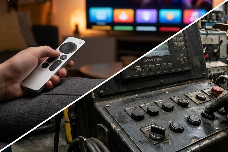
Silicone keypads are used wherever reliable, tactile human-machine interfaces are needed. They are particularly useful in environments where membrane switches fail and mechanical switches wear out.
| Industry | Representative Products | Key Requirements |
|---|---|---|
| Medical devices | Patient monitors, infusion pumps, surgical instruments, diagnostic equipment | IP67+ sealing, biocompatibility (ISO 10993), easy chemical decontamination |
| Industrial controls | PLCs, machine panels, test instruments, power tools | Oil/chemical resistance, wide temperature range (−40°C to +85°C), 5M+ cycle life |
| Military and defense | Radio handsets, ruggedized computers, vehicle controls, night-vision equipment | MIL-SPEC compliance, shock/vibration resistance, extreme temperature performance |
| Consumer electronics | TV remotes, calculators, gaming controllers, smart home hubs | Low cost, appealing aesthetics, 1–3M cycle life |
| Automotive | HVAC controls, infotainment systems, seat adjusters, key fobs | UV stability, thermal cycling (−40°C to +85°C), resistance to cleaning agents |
| Marine and aviation | Navigation panels, communication equipment, cockpit controls | IP68 sealing, salt spray resistance, vibration performance |
| Payment terminals | POS keypads, ATM PIN pads, kiosk interfaces | 10M+ cycle life, anti-tamper construction, easy decontamination |
Why Choose SKF for Your Keypad Manufacturing Project?
With years of experience in silicone manufacturing, SKF specializes in custom silicone keypad solutions for global clients.
Our capabilities include:
- in-house CNC mold manufacturing
- compression molding and multi-color silicone molding
- laser engraving and precision printing
- rapid prototyping services
- strict quality control systems
We support customers from concept design to mass production.
Whether you need industrial control keypads, automotive interfaces, or backlit silicone buttons, our engineering team can help optimize both performance and cost.
Ready to start?
Send us your keypad drawing, PCB layout, and application environment details. We will return a DFM review and production quote within 48 hours.
FAQ
What is the raw material for silicone rubber?
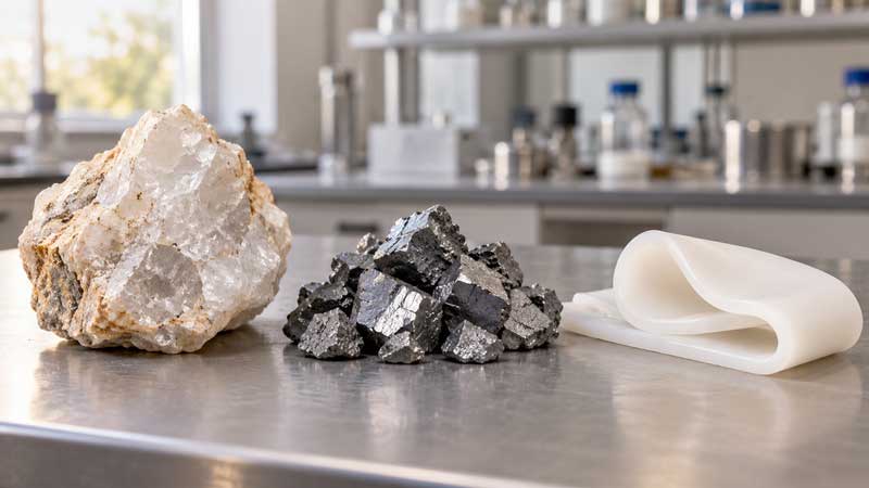
The base raw material is polydimethylsiloxane (PDMS) — a silicon-oxygen polymer — combined with reinforcing fillers such as fumed silica, pigments for color, and a peroxide or platinum curing agent depending on whether HCR or LSR is used.
Can silicone keypads be customized?
Yes. Key shape, Shore A hardness, actuation force, color, backlight type, legend method, IP sealing level, and conductive contact technology can all be specified to order.
How do you repair a silicone keypad that has stopped responding?
In most cases, non-responsive keys are caused by worn or contaminated carbon pills or oxidized PCB contact traces; cleaning the PCB contacts with isopropyl alcohol resolves contamination issues, while worn carbon pills require keypad replacement. Conductive repair paint can extend keypad life temporarily.
What are the main factors that affect the cost of a custom mold for a silicone keypad?
It depends on cavity count in one tooling (multi-cavity toolings reduce unit costs) and complexity for processes like two-shot molding or complex undercuts.
How do you ensure the legends do not wear off over time?
We offer protection ways for wear resistance of silicone keypads, including laser etching with permanent symbols on the surface, PU or epoxy coating, and two-shot molding for extreme environments.
Conclusion
SKF is a professional custom silicone keypad manufacturer with manufacturing capabilities and design solutions from geometry & layout design of keys, backlight, sealing demands, tooling creation, molding process selection, electrical contacts for conductivity, legend treatments, and surface finishes to final delivery. Hope our silicone keypads with fine design, selective materials, curing process, and quality control, as well as satisfactory services, can help you with your rubber keypad project.