Automotive Electronics Silicone Keypad Manufacturer
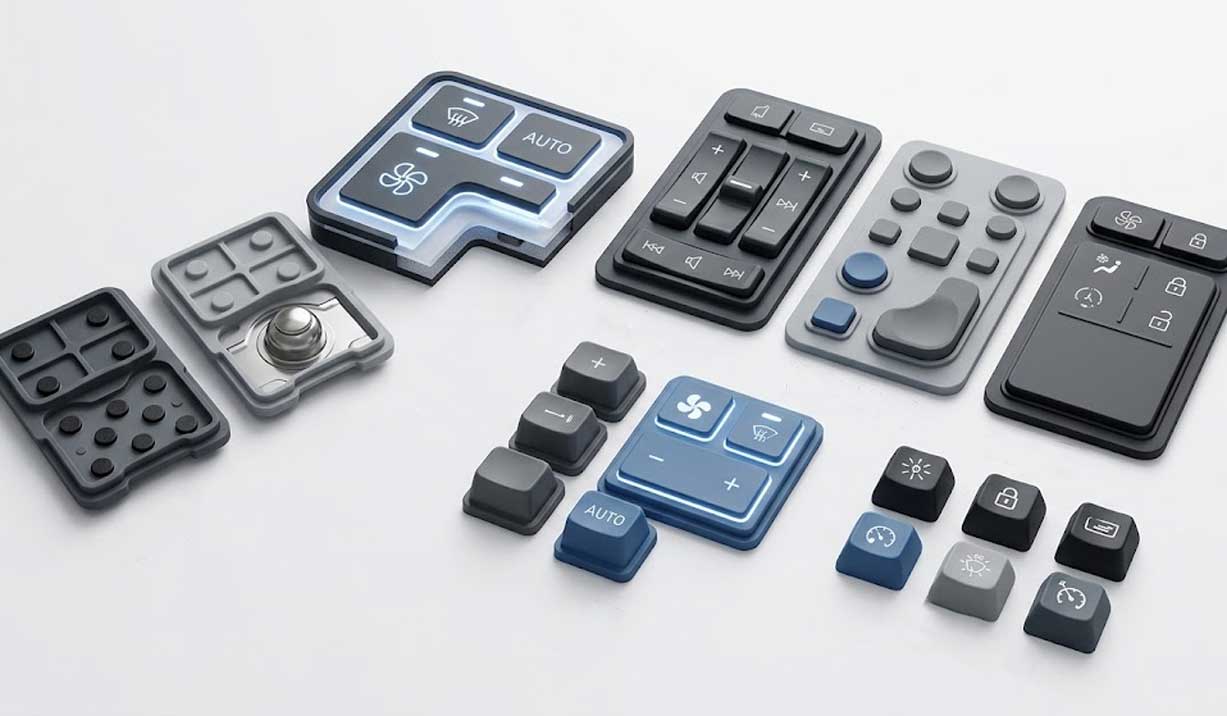
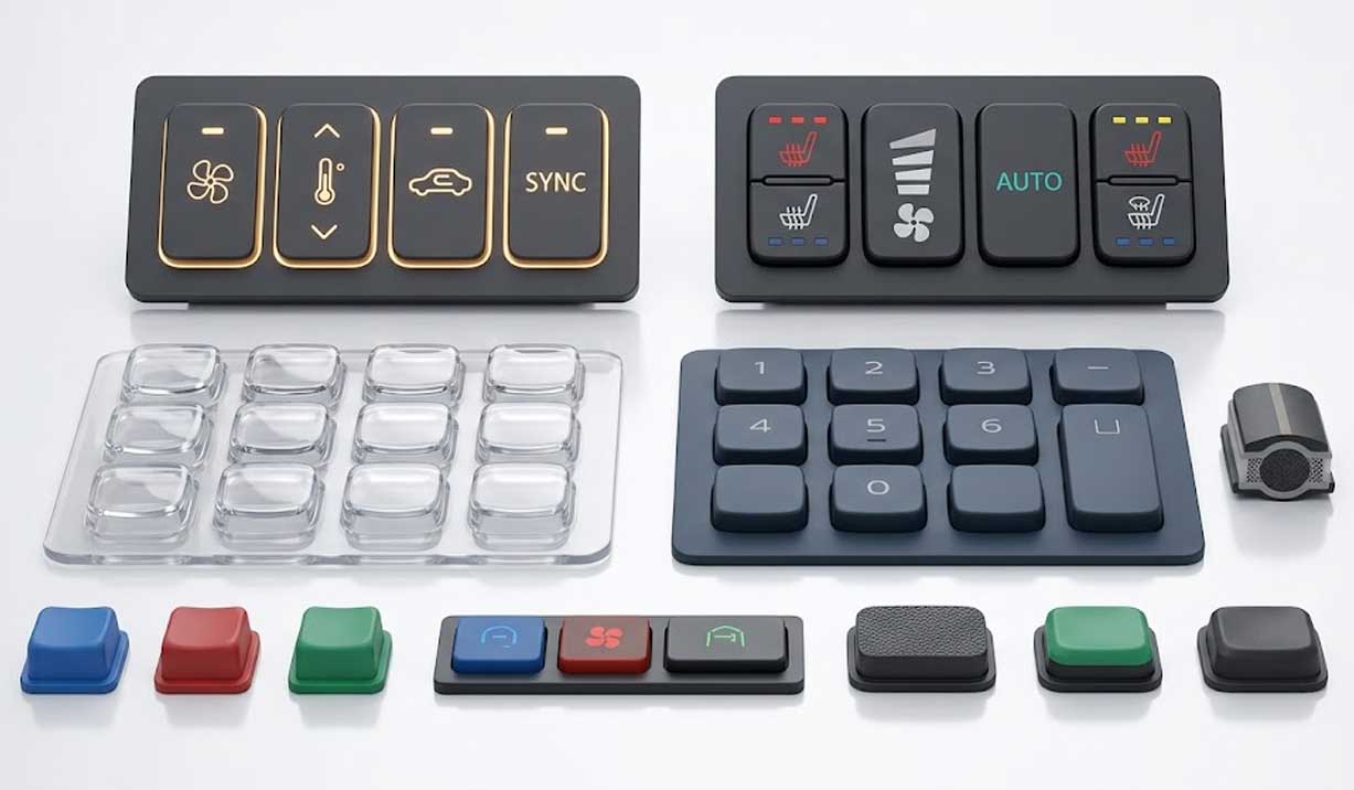
Automotive electronic equipment uses physical keypads for functions that still require direct tactile operation, including HVAC controls, steering-wheel switches, center-console controls, smart key fobs, EV controls, and other vehicle interface modules.
For these interfaces, the main engineering problem is not simply making a silicone button. The keypad must fit the available space, activate the PCB or FPC consistently, provide the required tactile response, remain stable under temperature changes and vibration, and maintain its graphics or backlighting after repeated use.
SKF develops automotive silicone keypads around these interface requirements. During development, the keypad structure is evaluated together with the PCB contact pattern, housing, button travel, sealing interface, surface treatment, and lighting system.
The result is a keypad designed for the actual vehicle interface rather than a generic silicone keypad adapted after tooling.
What Are Automotive Electronics Silicone Keypads?
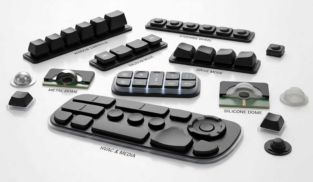
Automotive electronics silicone keypads are molded silicone input components used in vehicle electronic control interfaces. Typical equipment includes HVAC control panels, steering-wheel control modules, center-console switches, dashboard control panels, infotainment controls, smart key fobs, EV control interfaces, commercial vehicle control modules, and specialty vehicle electronic controls.
The keypad normally sits between the operator and an electronic switching system. Pressing a button moves the silicone web and conductive contact toward a PCB or FPC contact pad. The web geometry determines much of the tactile response, while the conductive structure determines how the electrical circuit is triggered.
This creates several engineering dependencies.
A change in silicone hardness can change actuation force. A change in web thickness can change snap response. A change in carbon pill diameter can affect contact alignment. A thicker surface coating can change the appearance and tactile feel of the key. A sealing rib that is too aggressive can increase compression and restrict button travel.
For this reason, automotive keypad development needs to consider the mechanical, electrical, optical, and sealing interfaces together.
The vehicle environment also changes the design requirements. Cabin temperatures vary significantly between cold starts and parked vehicles exposed to direct sunlight. Steering-wheel buttons experience continuous vibration and frequent thumb operation. Center-console buttons may be exposed to drinks, cleaning agents, dust, and skin oils.
The keypad structure therefore needs to be selected according to the actual equipment and operating conditions.
Automotive Electronics Keypad Challenges and Engineering Solutions
Challenge 1: Temperature Changes Can Alter Tactile Response
Automotive control interfaces may experience large temperature changes during vehicle operation and storage. Silicone properties can change with temperature, and the mechanical structure can respond differently as the material expands, contracts, or changes stiffness. If the keypad is designed only around room-temperature samples, the button force at the temperature extremes may not match the original target.
Engineering Solution
SKF evaluates the silicone compound, hardness, web geometry, button size, and target actuation force together. The web is particularly important because it controls much of the button movement. A change in web thickness or geometry can alter the force-travel curve even when the silicone hardness remains unchanged. For temperature-sensitive automotive interfaces, prototype testing should verify the force-travel behavior across the required temperature range rather than relying only on room-temperature measurements.
Challenge 2: Steering-Wheel Buttons Have Limited Space
Steering-wheel control modules have limited internal space for switches, PCB components, mechanical supports, and wiring. When buttons are placed too close together, accidental activation becomes more likely. When the web structure is compressed into a small area, neighboring keys can also influence each other's tactile response.
Engineering Solution
SKF reviews button spacing, keytop dimensions, web geometry, mounting features, and PCB contact positions before tooling. The external key shape does not need to follow the same dimensions as the internal conductive contact. The button can be shaped for thumb operation while the lower contact geometry is optimized around the PCB layout. Where several buttons are positioned closely together, the web structure can be separated or reinforced to reduce mechanical interference between adjacent keys.
Challenge 3: Frequent Pressing Can Change Tactile Performance
Automotive controls such as audio, phone, cruise-control, HVAC, and menu buttons may be pressed repeatedly throughout the vehicle's service life.Tactile changes can occur when the web structure is poorly designed, when stress concentrates around a small transition area, or when the return structure does not provide enough recovery force.
Engineering Solution
SKF adjusts web thickness, web angle, button geometry, silicone hardness, travel distance, and snap ratio during development. The target is not simply a high cycle count. The force-travel curve should remain within the agreed engineering range after repeated operation. For prototype validation, SKF can measure actuation force, travel, return force, and snap response before and after cycling. The testing approach is consistent with SKF's current keypad testing process, which evaluates tactile performance through force-travel measurement and repeated-operation validation.
Challenge 4: Liquids and Contaminants Can Reach the Electronics
Automotive control panels can be exposed to water, drinks, dust, skin oils, and interior cleaning agents. A conventional switch with exposed mechanical gaps can provide paths for contamination to reach the PCB or switching mechanism.
Engineering Solution
The silicone keypad can incorporate a perimeter sealing skirt, sealing lip, or compression interface between the keypad and housing. The sealing structure must be designed together with the enclosure. Simply adding a thicker rubber edge does not automatically create an IP-rated assembly. Compression, housing tolerance, gasket geometry, screw or clip position, PCB location, and drainage path all affect the final protection level. For projects requiring an IP rating, SKF evaluates the keypad as part of the complete enclosure rather than treating the silicone material itself as the IP protection.
Challenge 5: Backlit Symbols Must Work in Both Daylight and Darkness
Automotive controls often require visible symbols during the day and controlled illumination at night. If the opaque coating is too thick, the symbol may become dim. If the laser-etched area is too large, unwanted light can escape around the graphic. LED position and silicone thickness can also create bright spots or uneven illumination.
Engineering Solution
SKF coordinates the silicone translucency, coating structure, laser-etched area, symbol geometry, and LED position during development. The light window is treated as part of the keypad structure rather than as an artwork-only decision. Prototype samples should be checked under the intended LED configuration because the optical result can change after coating thickness, silicone thickness, and LED distance are finalized.
Challenge 6: PCB Contact Alignment Can Affect Switching Consistency
Automotive electronic keypads commonly use conductive carbon pills or other contact structures to trigger PCB or FPC circuits. A keypad may look dimensionally correct while the conductive contact is slightly misaligned with the PCB pad. This can reduce the effective contact area, increase contact resistance, or cause inconsistent switching between keys.
Engineering Solution
SKF reviews the carbon pill diameter, thickness, position, PCB pad size, contact pressure, key travel, and mechanical alignment together. The conductive contact is not positioned only according to the visible button center. Its location is determined by the actual PCB/FPC contact pattern. This is particularly important when the button layout is compact or when the PCB has limited clearance between neighboring switching points.
Equipment-Specific Automotive Silicone Keypad Applications

HVAC Control Panels
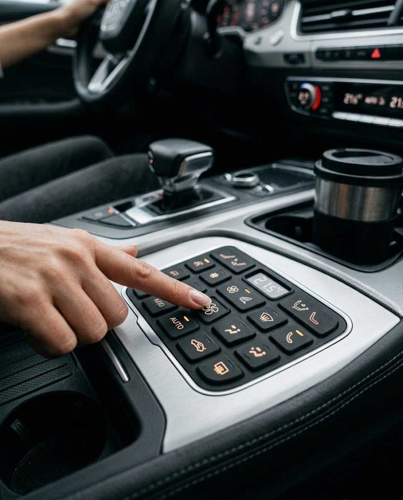
HVAC control panels are operated frequently and may be pressed while the driver is wearing gloves or while the vehicle is moving. Typical functions include temperature, fan speed, airflow direction, defrost, seat heating, and other climate controls. Common design issues include unclear tactile differentiation between adjacent buttons, excessive actuation force, poor nighttime visibility, and contamination around the control panel. SKF can use a medium actuation force with a defined snap response, controlled key spacing, carbon pill contacts matched to PCB pads, laser-etched or printed HVAC symbols, backlighting where required, and a sealing skirt around the keypad perimeter. A matte or low-gloss surface can also be selected to reduce visible reflections. The button geometry should allow the driver to identify adjacent functions through touch rather than relying entirely on visual inspection.
Steering Wheel Control Modules
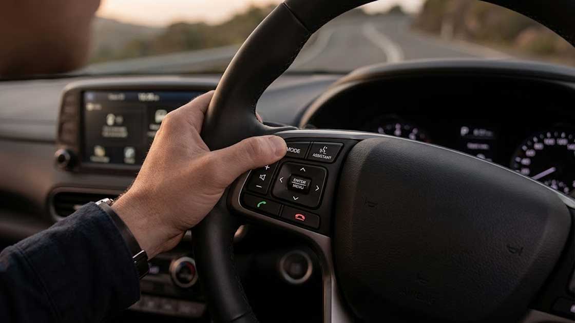
Steering-wheel control modules have limited installation space and are operated mainly by the driver's thumb. Typical functions include audio, phone, cruise control, voice assistant, menu navigation, and driver-information controls. Common problems include accidental activation, limited button travel, mechanical interference between neighboring keys, and inconsistent contact alignment. SKF can use a compact key layout, controlled key spacing, moderate tactile force, short and clearly defined travel, carbon pill or other approved contact structures, reinforced mounting features, low-profile web structures, and backlit legends where required. The internal web structure should be designed around the PCB and housing rather than simply copying the external button shape.
Center Console Controls
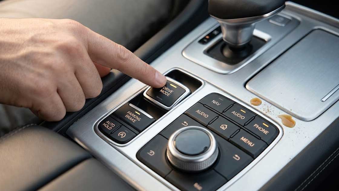
Center-console controls may be operated repeatedly by different users and can be exposed to drinks, food particles, dust, skin oils, and cleaning products. The available panel area can also be limited by surrounding displays, rotary controls, USB ports, and storage areas. These conditions require a sealed perimeter structure, PU or other protective surface treatment where necessary, clearly separated button functions, carbon pill contacts for PCB switching, printed or laser-etched legends, backlighting for nighttime operation, and web geometry optimized for repeated pressing. The housing compression should be checked during assembly because excessive compression can increase button force and reduce the available travel.
Smart Key Fobs
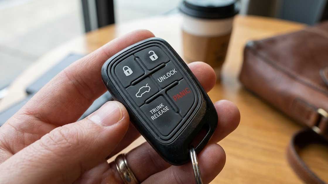
Smart key fobs are handled frequently and may be carried in pockets or bags or exposed to moisture and skin oils. The available keypad area is small, so individual buttons may need to remain visually and tactically distinguishable. SKF can use compact button geometry, low-profile web structures, defined tactile differentiation, conductive carbon pills or alternative contact structures, wear-resistant surface treatments, high-contrast or molded legends, and perimeter sealing where required. The keytop should not be made excessively large simply to increase contact area. The internal contact geometry can instead be optimized independently around the PCB.
EV Control Interfaces
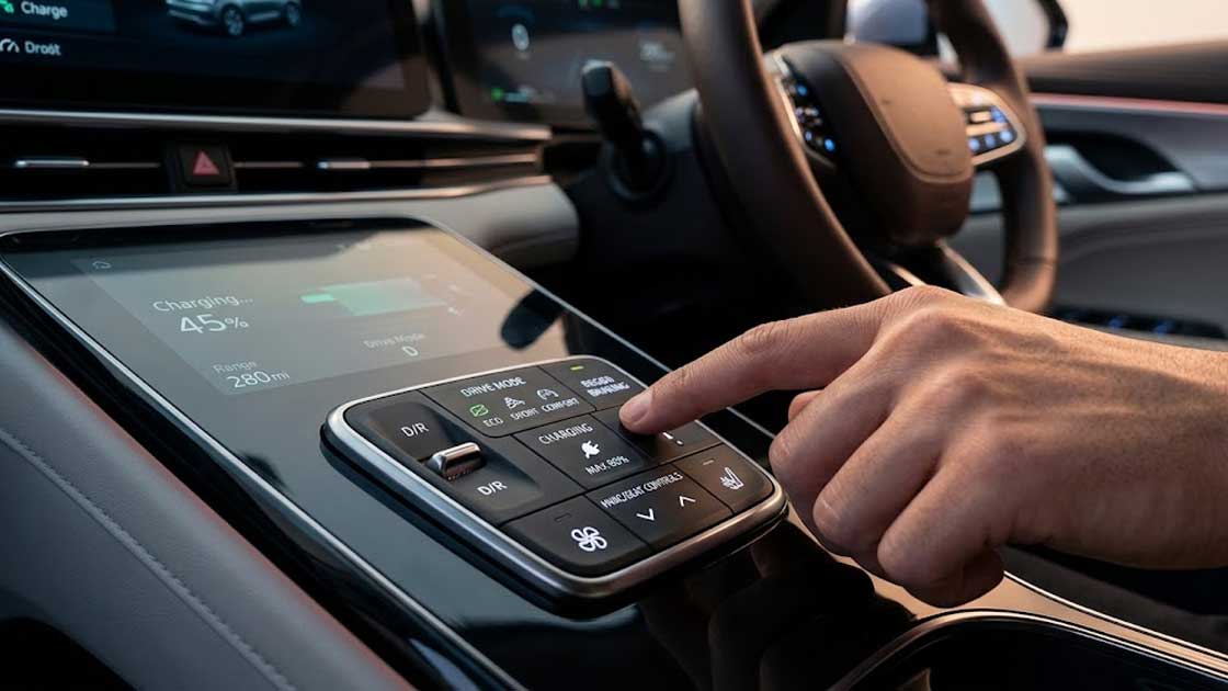
EV control interfaces can combine conventional physical buttons with touch displays and electronic control modules. The keypad may be used for drive-mode selection, charging-related functions, HVAC controls, seat controls, or other frequently accessed functions. Typical design issues include limited panel space, strong styling requirements, backlighting, and the need for clear tactile differentiation between physical controls and surrounding touch interfaces. SKF can use a compact multi-function layout, controlled tactile force, backlit symbols, laser-etched legends, conductive carbon contacts, surface coatings selected for repeated touch, and sealing where the control module requires environmental protection. The tactile response should remain clearly distinguishable from the surrounding touch interface so the operator can identify the physical control without continuously looking at it.

Commercial Vehicle Control Panels
Commercial vehicle control panels can be exposed to higher vibration, longer operating hours, glove operation, dust, and more frequent cleaning. Buttons may also be larger and require stronger tactile feedback than passenger-vehicle controls. SKF can use higher tactile force where glove operation requires it, larger keytops, wider key spacing, high-cycle web structures, carbon pill contacts, PU-protected graphics, sealed perimeters, and surface textures selected for grip and contamination control. The final actuation force should be verified with the actual glove and operator requirements rather than selected only from a standard keypad specification.
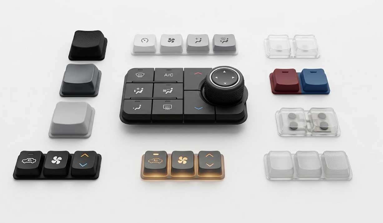
Key Design Considerations for Automotive Electronics Keypads
Button Layout
Button spacing affects both operating speed and accidental activation. Buttons that are too close together can be difficult to distinguish by touch. Excessive spacing, however, wastes limited dashboard or steering-wheel area. SKF evaluates keytop size, center-to-center spacing, surrounding housing features, finger or thumb movement, and PCB contact positions together. For compact interfaces, visual spacing and mechanical spacing should not be treated as the same dimension. A raised key edge or different key shape can provide additional tactile separation without significantly increasing the overall panel footprint.
Actuation Force
Actuation force determines how much pressure the operator must apply before the electrical switch is triggered. Low-force buttons can reduce finger effort, but excessive reduction can make accidental activation more likely. Higher force can provide stronger confirmation, but may become uncomfortable when a button is operated repeatedly. The appropriate force therefore depends on the control function, button size, operating position, and expected frequency of use. SKF can adjust force through the combination of silicone hardness, web thickness, web angle, button geometry, travel distance, and snap ratio rather than relying on hardness alone.
Snap Ratio
Snap ratio describes the relationship between peak actuation force and the force after the tactile transition. A sharper snap can make the switching point easier to identify. A softer response may be more appropriate for certain compact or frequently operated controls. Web geometry has a major influence on snap response. Changing the web angle, thickness, transition radius, or supporting structure can change the force-travel curve without changing the visible keytop. This is why tactile adjustment should normally be performed during prototype development before the production mold is finalized.
Carbon Pill Positioning
The conductive carbon pill must reach the PCB contact pad with sufficient contact pressure and alignment. Important parameters include carbon pill diameter, pill thickness, pill resistance, PCB pad diameter, contact spacing, contact pressure, vertical travel, and alignment tolerance. A larger carbon pill does not automatically improve switching. It may increase contact area but reduce electrical clearance between neighboring pads. SKF therefore reviews the carbon pill and PCB layout together during development. SKF's current conductive keypad specifications list carbon-pill contact resistance below 100 Ohms as a reference value, while the actual target should be established according to the customer's circuit requirements.
Sealing Design
A silicone keypad can act as part of the interface seal when its perimeter structure is correctly compressed against the housing. Typical structures include perimeter sealing skirts, sealing lips, compression ribs, integrated gasket areas, and raised sealing walls. The sealing design must consider housing flatness, compression ratio, screw or clip positions, keypad thickness, and PCB location. For IP-rated equipment, the keypad should be tested as part of the complete assembly. The silicone keypad alone cannot guarantee IP67, IP68, or another enclosure rating.
Surface and Legend Design
Automotive buttons can use screen printing, laser etching, molded legends, PU coating, UV coating, or combinations of these processes. The correct process depends on the required symbol appearance, backlighting, abrasion exposure, cleaning method, and expected operating cycles. For frequently touched controls, the graphic process should be validated after abrasion or chemical exposure rather than checked only immediately after production.
Request an Automotive Silicone Keypad Engineering Review
If you are developing automotive electronic equipment, SKF can review the keypad structure, tactile requirements, PCB/FPC interface, sealing design, surface treatment, and backlighting requirements before tooling.
Send your 2D drawing, 3D model, PCB layout, existing keypad sample, or basic equipment requirements.
The earlier the keypad structure is reviewed, the easier it is to identify problems such as excessive actuation force, carbon-pill misalignment, insufficient sealing compression, uneven backlighting, or difficult molding before production tooling is finalized.
Manufacturing Insight: Automotive Keypad DFM and Production Control
Automotive keypad problems are often created before molding begins. Before tooling, SKF reviews the keypad layout, button spacing, web geometry, PCB contact area, sealing structure, graphic location, and demolding direction. This review helps identify several common risks.
Web Thickness and Tactile Variation
A small change in web thickness can change actuation force. If neighboring buttons have different web geometries, they may produce noticeably different tactile responses even when the keytops look identical. SKF therefore reviews the web structure before tooling and uses force-travel testing during validation.
Mold Structure and Flash
Automotive keypads often contain thin webs, small gaps, sealing ribs, and detailed button graphics. These areas require suitable mold parting lines and venting. Poor parting-line placement can create flash around functional areas. Excessive flash around a sealing structure can interfere with assembly or change compression.
Conductive Pill Position
The conductive pill must remain within the PCB contact tolerance after molding and trimming. SKF checks the relationship between the pill location, mold cavity, keypad geometry, and PCB contact pattern rather than relying only on the external key dimensions.
Printing and Laser Alignment
Graphics are positioned relative to the molded key structure. During production, the reference for printing or laser etching must account for the actual molded part rather than treating the artwork as an independent flat image. This is especially important when symbols must align with LED windows or PCB-mounted light sources.
Surface Coating Validation
PU or UV coatings can improve resistance to abrasion, but coating thickness and adhesion need to be controlled. For backlit keypads, excessive coating can reduce light transmission. For tactile surfaces, the coating can also change the perceived surface feel.
Production Inspection
Automotive keypad inspection can include dimensional inspection, visual inspection, actuation-force testing, travel measurement, snap-ratio analysis, conductive contact resistance testing, graphic alignment, coating adhesion, lifecycle testing, and assembly fit. SKF's manufacturing and testing information identifies tactile force, snap ratio, travel, contact resistance, visual alignment, abrasion, alcohol-rub, and lifecycle testing as relevant keypad inspection areas.
Automotive Silicone Keypad Customization Options
Customization should be based on the equipment requirement rather than simply changing the appearance of a standard keypad.
Silicone hardness
Hardness affects the force required to move the button, but the final tactile response also depends on web geometry.
Temperature requirement
The silicone compound should be selected according to the actual operating and storage temperature range.
Chemical resistance
If the keypad will contact interior cleaners, oils, sweat, fuel, or other specified chemicals, the material and coating should be evaluated against those substances.
Carbon pill
Used to bridge PCB or FPC contacts. Diameter, thickness, resistance, and location are matched to the electrical layout.
Metal dome
Can be combined with silicone structures when a different tactile response or switching mechanism is required.
Backlighting
Translucent silicone, laser-etched windows, opaque coating, and LED positioning can be combined to produce illuminated legends.
LED integration
The keypad can be designed around the LED position and optical path when the PCB layout requires controlled light transmission.
Screen printing
Suitable for fixed-color legends and symbols.
Laser etching
Useful for backlit symbols because the laser removes the opaque surface layer to expose the translucent area.
PU coating
Used where additional surface protection is required.
Epoxy coating
Can create a harder raised or glossy surface for specific button designs.
Water-resistant or sealed design
Perimeter skirts, ribs, or gasket structures can be incorporated where the housing requires a sealed interface.
Key shape
Different keytop profiles can be used to improve visual or tactile differentiation.
Travel distance
Travel can be adjusted according to the required tactile response and PCB switching distance.
Tactile force
Force can be modified through silicone hardness, web geometry, button dimensions, and snap structure.
Technical Specifications for Automotive Silicone Keypads
| Parameter | Typical Range / Option |
|---|---|
| Silicone Hardness | 40–70 Shore A commonly used; broader material options available |
| Actuation Force | Approximately 150–250 g for many automotive control designs; project dependent |
| Key Travel | Approximately 0.8–2.5 mm; design dependent |
| Contact Method | Carbon pill, metal dome, or other approved contact structure |
| Carbon Pill Contact Resistance | <100 Ohm reference for standard carbon-pill designs |
| Lifecycle | 1 million+ cycles commonly targeted; higher requirements require design validation |
| Operating Temperature | Approximately -40°C to +200°C depending on compound and application |
| Surface Treatment | Screen printing, laser etching, PU coating, UV coating, epoxy |
| Protection Design | Sealing skirt, gasket interface, compression rib, or integrated sealing structure |
| Backlighting | Translucent silicone + laser-etched or printed light window |
| Key Layout | Application-specific |
| Color | Application-specific |
| PCB/FPC Interface | Custom according to contact-pad layout |
SKF’s current automotive application page lists 150–250 g actuation force, 40–60% click ratio, and IP67–IP69K as application references. These figures should not be treated as automatic specifications for every design because the final result depends on the complete keypad and enclosure.
Why OEM Customers Work With SKF for Automotive Keypads
Engineering Support
SKF can review:
- 2D drawings
- 3D models
- PCB/FPC contact layouts
- Existing keypad samples
- Actuation-force requirements
- Key travel
- Sealing structures
- Backlighting requirements
The purpose of the review is to identify design risks before tooling.
Prototype Validation
Prototype samples can be used to verify:
- Button dimensions
- Key spacing
- Actuation force
- Travel
- Snap response
- Carbon pill alignment
- Contact resistance
- Graphic position
- Backlighting
- Housing fit
This allows tactile and electrical problems to be corrected before production tooling is locked.
Tooling Development
The mold must accommodate the web structure, button geometry, conductive elements, venting, parting lines, and demolding requirements.
Automotive keypad tooling is therefore reviewed around both the external appearance and the functional structure underneath each button.
Manufacturing Processes
SKF’s keypad manufacturing process can include:
- Silicone compression molding
- LSR molding where appropriate
- Conductive contact integration
- Screen printing
- Laser etching
- PU/UV coating
- Epoxy treatment
- Deflashing and trimming
- Assembly
The appropriate process depends on the keypad geometry and required surface or electrical structure.
Quality Validation
Relevant inspection can include:
- Dimensional inspection
- Actuation-force measurement
- Force-travel curve
- Snap-ratio analysis
- Contact-resistance testing
- Graphic alignment
- Surface inspection
- Coating validation
- Lifecycle testing
SKF’s testing service specifically identifies force-travel testing and conductive contact-resistance testing as part of keypad reliability validation.
Automotive Silicone Keypad FAQ
How are silicone keypads integrated into automotive electronic equipment?
The keypad is normally positioned between the external housing and the PCB or FPC.
When the operator presses a button, the silicone web moves the conductive contact toward the PCB pad. The housing controls the keypad position while the web structure determines much of the tactile response.
The exact mounting method depends on the equipment architecture.
Can automotive silicone keypads achieve IP67 or IP68 protection?
They can contribute to an IP-rated assembly when the keypad includes an appropriate perimeter sealing structure and is correctly compressed against the housing.
However, the IP rating must be verified on the complete enclosure.
Keypad geometry, housing tolerances, compression, assembly method, PCB sealing, and test conditions all affect the final result.
How is tactile force adjusted?
Tactile force is influenced by:
- Silicone hardness
- Web thickness
- Web angle
- Web length
- Button size
- Button height
- Travel distance
- Snap structure
SKF can modify these parameters during prototype development to achieve the required force-travel response.
What causes inconsistent tactile response between buttons?
Common causes include differences in web geometry, molding variation, silicone thickness, button dimensions, or support conditions.
If two buttons use different web structures, they can produce different force curves even when the visible keytops are identical.
This is why the web geometry should be controlled during tooling and checked through force-travel testing.
How does SKF prevent carbon-pill contact problems?
The conductive pill is positioned according to the PCB/FPC contact layout.
SKF considers pill diameter, resistance, thickness, contact pressure, travel, and alignment rather than positioning the pill only by the visual center of the button.
The final contact performance should be verified through resistance and switching tests.
Can an existing automotive keypad design be improved?
Yes.
An existing sample can be evaluated for:
- Excessive actuation force
- Weak tactile response
- Poor key return
- Contact instability
- Insufficient sealing
- Graphic wear
- Backlighting problems
- PCB alignment
- Excessive button size
- Limited key spacing
The original sample, PCB layout, housing, and target operating conditions provide useful information for identifying which parameter should be changed.
Can SKF develop a keypad from an existing sample?
Yes.
A physical sample can be used as a starting reference for dimensions, button layout, tactile response, surface finish, graphics, and contact structure.
For a functional replacement, PCB/FPC and housing information is also recommended because the external shape alone does not define the electrical and mechanical interface.
What information is needed for an automotive silicone keypad quotation?
For an engineering quotation, provide as much of the following as possible:
- 2D drawing
- 3D model
- Existing sample
- PCB/FPC drawing
- Key count
- Key layout
- Target actuation force
- Key travel
- Contact type
- Silicone hardness
- Color
- Surface finish
- Graphic artwork
- Backlighting requirements
- Sealing requirements
- Annual quantity
- Prototype quantity
- Required tests
- Target market
If some information is not available, SKF can begin the review from the available drawing or physical sample and identify the missing parameters.