
P+R Plastic Rubber Keypads Manufacturer
SKF develops custom P+R plastic rubber keypads with rigid caps over molded silicone bases. The combination gives device controls a firm touch surface, elastic return and flexible options for legends, color and illumination. This page shows design configurations, typical targets and the assembly checks that matter before release.

What Are P+R Plastic Rubber Keypads?
P+R combines a rigid plastic keycap with an elastic silicone rubber keypad beneath it. The cap gives the user a defined hard surface and carries the visible color, texture or legend. The molded silicone section flexes when pressed and returns the key to its rest position. Depending on the circuit, a carbon pill on the underside closes a PCB contact, or the silicone actuator presses a metal dome or membrane switch.
The plastic and silicone parts are made separately and then joined or mechanically retained. Their combined height, alignment and fit in the enclosure determine whether each key moves freely and actuates at the intended point. The silicone base may also form a perimeter seal, but the finished device’s ingress rating depends on the whole enclosure and assembly.
These hybrid keypads are used in handheld controllers, payment terminals, instruments and other compact interfaces that need a firm, precise-looking key surface with the spring action of silicone. Choose P+R when the visible key design is difficult to achieve with an exposed all-silicone top; choose an all-silicone keypad when a simpler one-piece surface is the priority.
P+R Keypad Design Gallery
These six P+R keypad designs show how plastic cap shape, finish and switch layout can serve different devices. SKF develops each keypad around the enclosure, controls and appearance requirements of the project.
Compact Numeric Keypad
Wide-Key Control Pad
Backlit Navigation Cluster
Clear Gloss Instrument Pad
Color-Coded Function Pad
Compact Six-Key Function Pad
Where Do P+R Keypads Make Sense?

Payment Terminals and Data Entry
In a payment terminal, separate raised plastic number caps give repeated data entry a firm, clearly defined key surface. The compact grid follows a familiar number sequence, while red CANCEL and green ENTER keys distinguish the two end-of-entry actions. A molded silicone base beneath the caps provides elastic return and keeps the keypad together as one component. This combination gives handheld and countertop terminals readable, easy-to-locate controls without spreading the numbers across a large panel. Key spacing and bezel fit can then be tailored to the device.

Industrial Handheld Controls
An industrial handheld controller can place its core commands on large, separate plastic caps that stand out against a dark housing. In this layout, green START, red STOP and blue RESET keys carry bold white labels that remain easy to identify while the operator wears gloves or moves between workstations. The hard keytops provide obvious finger targets, and the silicone base returns each key after a press. Keeping the three commands together makes the controller direct to use without crowding the grip area. Final spacing and protection against accidental presses are set around the actual device.

Instruments and Low-Light Interfaces
A benchtop instrument can use dark plastic keycaps with illuminated POWER, MODE and SET legends to keep essential controls readable in subdued light. The three raised caps form a tidy strip that a gloved operator can find and press without brightening the whole panel. Plastic provides a firm, wipeable key surface, while the silicone base supplies elastic return beneath the caps. Cap finish, legend construction and the specified cleaning routine can be selected together for the instrument. For a single-material illuminated interface, see backlit silicone keypads.
How Can the Keypad Be Specified?
Plastic cap and visible finish
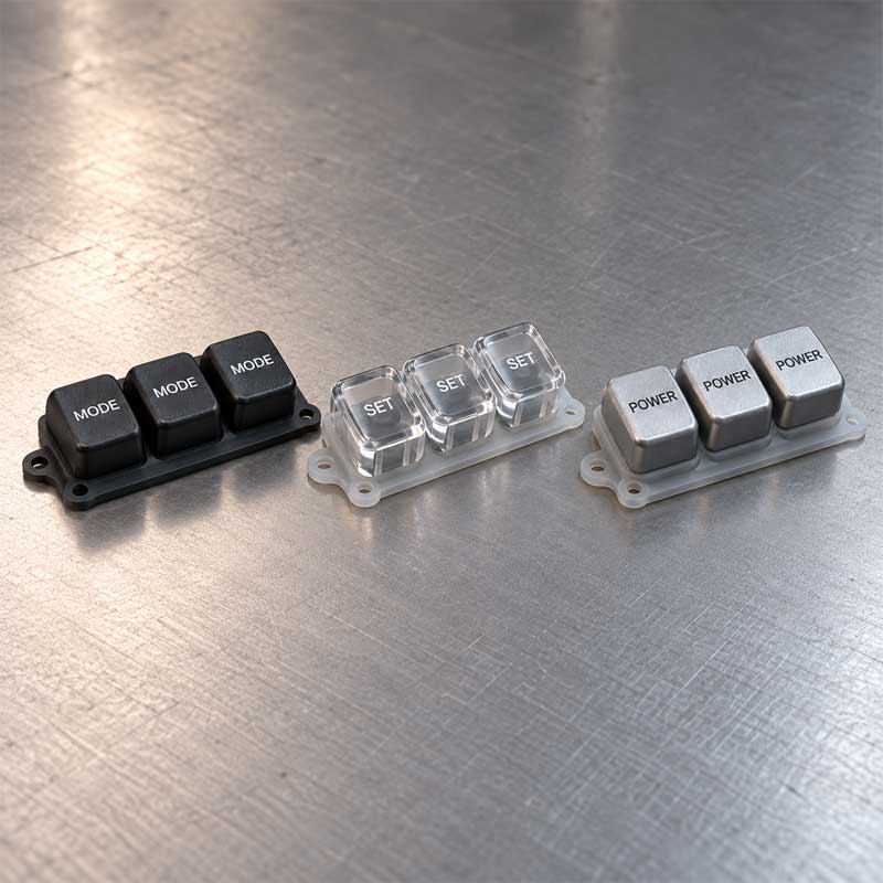
ABS suits many opaque colored caps; PC is useful when impact performance or optical transmission matters; PMMA can provide high clarity for selected visual designs. Resin grade, finish and marking method should be chosen together. Screen or pad printing supports colored graphics, while painted and laser-opened legends can create illuminated characters. A hard coat or protective finish may be considered where finger abrasion or cleaning is significant.
Silicone base and switch interface
The silicone base can be shaped for key height, pitch, web geometry, perimeter flange and locating features. Carbon pills are an option for direct PCB switching; a nonconductive actuator can press a metal dome or membrane contact. The switch choice changes the force curve and the way the assembly is tested. SKF’s tactile silicone keypads page explains the silicone web and force response in more detail.
Assembly scope
SKF offers custom P+R keypads as joined cap-and-silicone components or broader subassemblies that include the required switch layer. Cap marking, coating, retention method and switching are specified as one stack rather than separate cosmetic decisions. The number of unique cap shapes, colors, molds and assembly operations affects tooling and unit cost.
What Controls Feel, Alignment and Reliability?
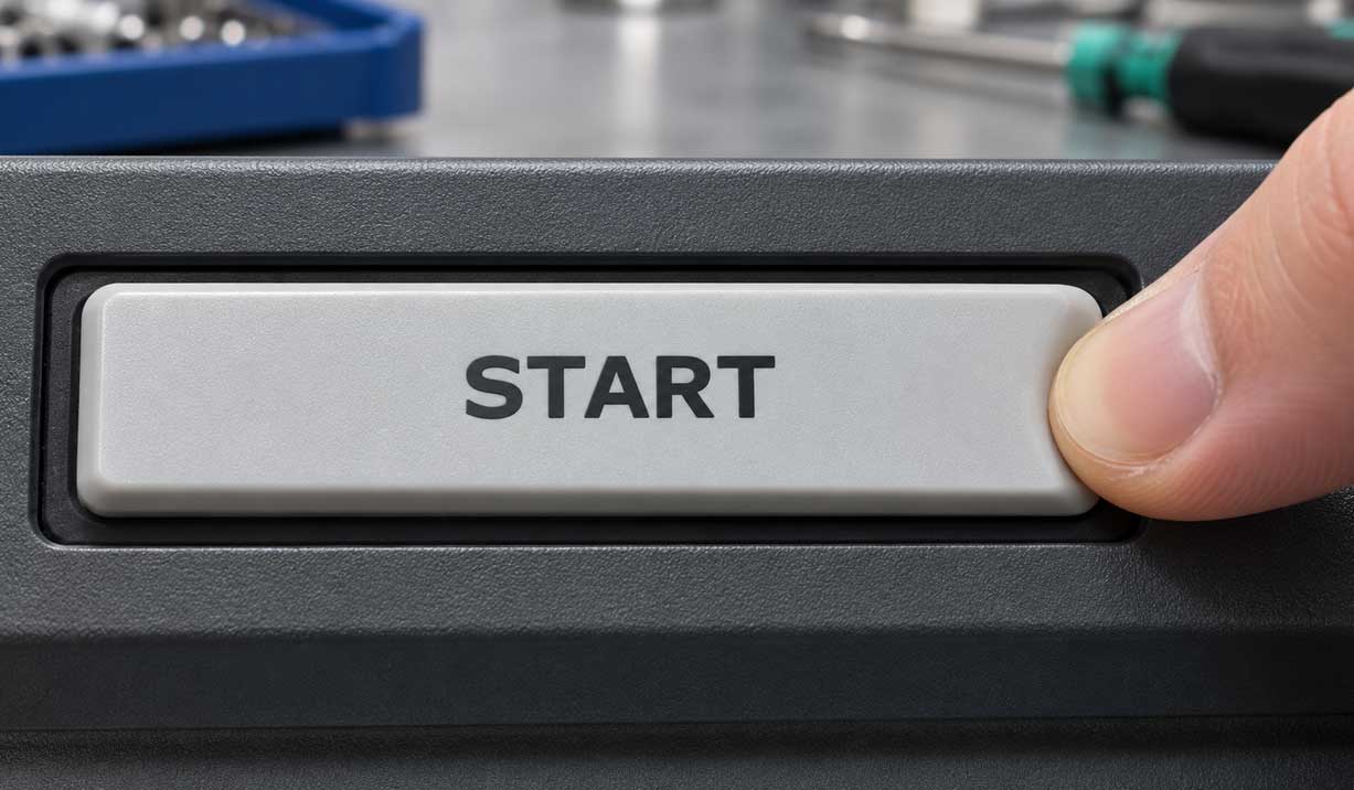
A plastic cap distributes finger force but also adds mass and a second material interface. Adhesive bonding needs enough clean, compatible contact area; a captive design relies on cap and housing geometry. If the cap is too wide for the silicone support, an off-center press can tilt it, rub the bezel or overload one side of the web. Retention and key movement should be checked after repeated presses, temperature exposure and the intended cleaning routine.

Silicone hardness alone does not set key feel. Web thickness, angle and height control the force peak and return; the cap weight, housing stop and switch actuation point alter what the user feels. A short travel can suit a compact device, but too little clearance can leave the key preloaded or cause a missed switch. Prototypes should be assessed with a force–travel curve, return force and full assembled travel, including tolerance extremes.
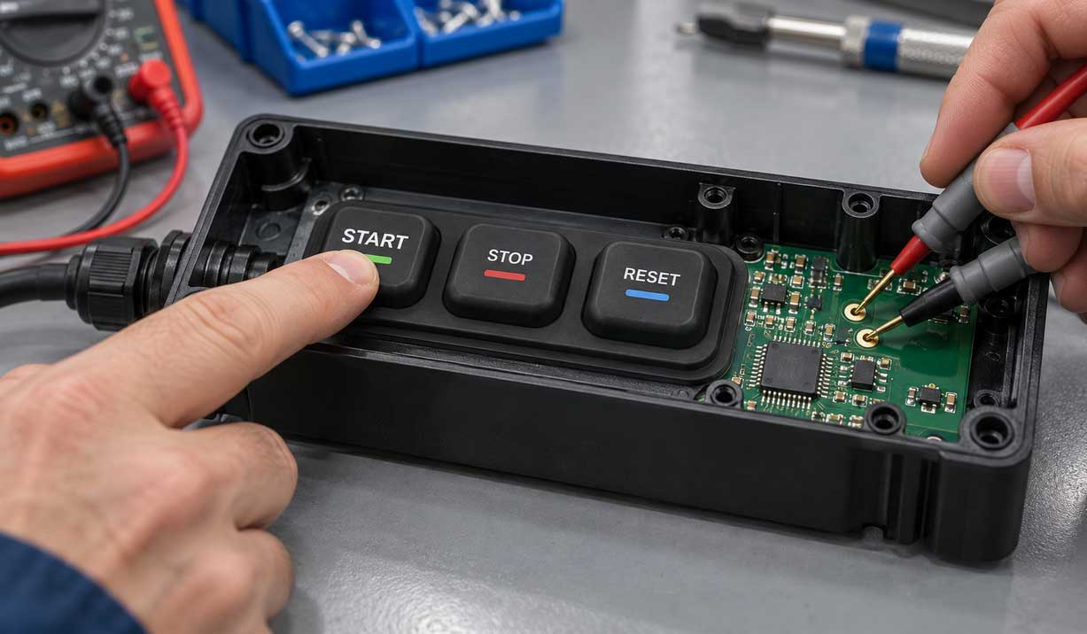
For carbon-pill switching, the contact must land on the PCB pattern with enough force and clearance after the key reaches the designed travel. For a metal dome, the silicone actuator, dome and housing stop must not compete for the same stroke. PCB height, bezel opening and silicone flange compression should be reviewed together; excessive compression can change button feel, while insufficient compression can weaken sealing. Electrical tests belong on the intended circuit geometry, not only on a loose keypad sample.
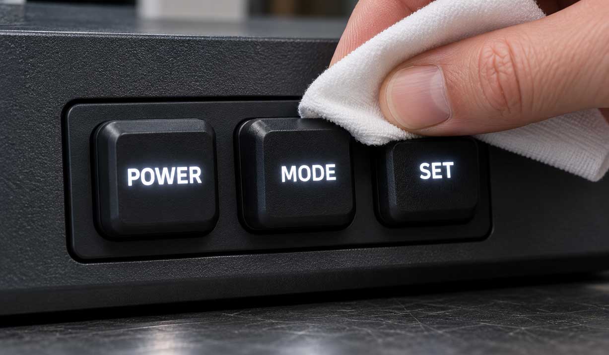
Illumination needs an optical path through the cap or legend and enough separation between neighboring keys to control light bleed. Printed, painted and coated cap finishes age differently under rubbing, solvents and UV. Sample approval should cover both appearance and functional checks after the specified exposure, especially when a clear cap is bonded over a decorated layer.
P+R Keypad Design as One Assembly
SKF develops P+R keypads around the complete cap, silicone, switch and enclosure interface. We can define the cap, contact and validation route for a new design or replacement part. Contact SKF to discuss your project, even at an early stage.
How Are P+R Keypads Developed and Checked?
Development starts with the assembled stack: cap profile, silicone web, switch position, PCB, bezel and any sealing land. Cap and silicone tooling are considered separately, then the joining or retention fixture is designed around alignment and bond placement. Early samples establish appearance, feel and fit before production details are frozen.
During sampling, cap dimensions and finish, silicone thickness, bond position and assembled height can be inspected. Functional checks include center and edge actuation, force–travel response, return, switch continuity or contact resistance, and cap retention. If the application requires it, add life cycling, temperature conditioning, cleaning exposure, abrasion, optical checks and complete-device ingress testing. Acceptance limits and test conditions should be set for the actual configuration.
After approval, the controlled process covers molded parts, surface marking, joining and final inspection. A cap may look correct while sitting slightly off-center or restricting travel, so inspection needs to include the assembled key rather than only individual parts. SKF’s silicone keypad prototyping service supports evaluation of keypad geometry and function before volume production.

P+R Keypad Design Specifications
The ranges below are starting design targets for a custom assembly. They are selected with the cap, silicone web, switch and enclosure together; the approved drawing and sample define the production specification.
Specification | Typical Design Range / Option | Design Consideration |
Plastic cap | ABS, PC, PC/ABS or PMMA | Select grade for appearance, impact, light transmission and cleaning |
Silicone hardness | 40–70 Shore A | Web geometry also controls force and return |
Actuation force | 80–300 gf per key | Measure on assembled keypad at the specified press point |
Key travel | 0.5–2.0 mm | Allow for switch point, stop and tolerance stack |
Carbon-pill contact | <200 Ω design target | Specify PCB pattern, finish and test force |
Mechanical life | ≥1,000,000 presses design target | Validate cap retention and switching after cycling |
Switch options | Carbon pill, metal dome or membrane actuation | Circuit and tactile response differ |
Operating temperature | Set for selected plastic, bond and silicone grades | The assembled product cannot inherit the silicone-only rating |
Ingress protection | Set at device level; test to IEC 60529 if required | Depends on bezel, flange and enclosure compression |
The P+R assembly needs plastic-cap and silicone tooling plus a joining operation. MOQ, lead time, tolerance, bond-strength criterion and supply scope are set by the approved design and production route rather than by one standard catalog specification.
Why Work with SKF on This Keypad?
SKF develops the plastic caps, silicone base and contact interface as one keypad assembly. We set tactile targets through the silicone web and selected switch, then evaluate cap fit and key travel in the enclosure. An assembled sample makes appearance, feel and clearances reviewable before the production design is frozen.
The plastic caps require separate tooling and a controlled joining route. We define cap marking, retention and inspection around the approved design, so visible details and switching performance are checked together before volume production.
Why Work with SKF on This Keypad?
Can a P+R design reuse an existing PCB?
Often it can, if the contact pattern, switch height and available travel remain compatible. Adding a plastic cap changes the stack height and may require a new bezel opening or stop. Fit and switching should be verified with an assembled sample.
Is a bonded cap always the best choice?
No. Bonding suits many individual cap layouts, while a guided or mechanically retained cap may handle wider keys or side loading better. The choice depends on cap geometry, available bond area, expected use and service requirements.
Can the same silicone base support different cap colors or legends?
Often yes, when the cap footprint, attachment area and key load remain the same. A new legend or color may change the marking process or material approval, but it need not change the silicone tool. Recheck illumination and wear if the surface finish also changes.
Can SKF discuss a replacement keypad without original CAD?
Yes. An existing part or an early concept can start the discussion. The electrical and enclosure interfaces can be established during design review before a production specification is finalized.