
Backlit Silicone Rubber Keypads Manufacturer
Backlit silicone rubber keypads make controls readable when ambient light is low. For an OEM device, the illuminated artwork also has to work with the key feel, electrical contacts, PCB and housing. SKF develops custom, multi-key silicone keypads around those requirements. This page explains the main configurations, the design choices behind a working sample, and how SKF supports development.

What Are Backlit Silicone Rubber Keypads?
Backlit silicone rubber keypads are molded, multi-key components designed to let light pass through selected legends, key surfaces or indicator windows. LEDs on the device PCB commonly provide the light; the silicone keymat forms the touch surface and allows each key to move and return. A conductive contact or molded actuator operates the circuit beneath the key. The keypad may also form part of the panel interface, although any sealing performance depends on the finished assembly.
Their main purpose is to make controls easy to locate and identify in low light while preserving a usable key press. They are used in equipment such as industrial panels, handheld instruments, payment or access terminals, and vehicle controls. Because the same interface must often work with the lights off, daytime contrast matters too. An OEM backlit keypad is therefore specified with its artwork, LED, PCB and housing rather than as an isolated rubber part.
Backlit Silicone Keypad Features at a Glance
Selective illumination
Legends, key areas and status windows can be assigned different lit states, so the light communicates the intended function.
Molded keymat geometry
Key shape, spacing, height and mounting edge are built around the enclosure rather than forced into a stock layout.
Defined key response
Web structure and the selected switch interface establish how each key actuates and returns.
Matched surface artwork
Molded color, opaque areas and opened legends are selected for both powered and unpowered readability.
Choose What Needs to Light Up
A backlit keypad can reveal only the legends, illuminate a larger key area, or combine keys with separate status indicators. Choosing the visible effect first helps determine the silicone color, surface treatment and light path. The configurations below show how that choice changes the construction.
Configuration | Suitable when | Design consequence |
Illuminated legends | Symbols must be legible at night while the key surface remains dark. | A light-transmitting base and opaque surface can be combined with opened legends; artwork, coating and LED position determine clarity. |
Illuminated key area or window | The operator must find a whole key, a border or a status window quickly. | Window shape, silicone thickness and off-state appearance need to be reviewed alongside the housing. |
Separate lighting zones | Key groups or indicators change state independently. | LED placement, masking and any light guide must limit light spreading into adjacent zones. |
Direct LEDs on the customer’s PCB are a common starting point. Where space or the desired appearance makes direct lighting unsuitable, a separate light-distribution feature may be evaluated. The SKF backlighting options guide covers the broader lighting methods; this page focuses on the rubber keypad that must fit the finished interface.
Versatile Solutions for Demanding Sectors

Sector 01
Industrial Control Panels
In complex automation lines or heavy machinery, ambient lighting is often insufficient. Our backlit keypads, with **IP67 rated protection**, ensure clear visual guidance in wet, dusty, or oily environments, significantly reducing the risk of operation errors.
Protection
IP67 Waterproof / Dustproof
Durability
1,000,000+ Actuations
Sector 02
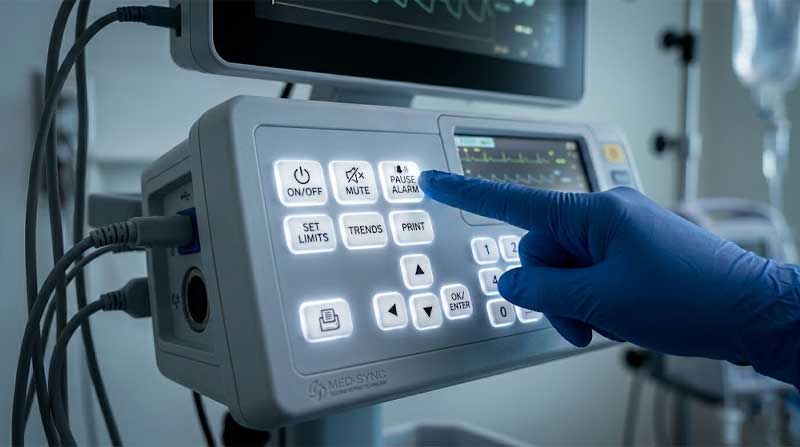
Medical Diagnostic Devices
Medical environments demand high material safety and soft backlighting. We provide **FDA compliant** medical-grade silicone with special light-diffusion layers, ensuring comfortable and precise control for healthcare professionals in operating rooms or monitoring labs.
FDA Compliant
Anti-Microbial
Sector 03
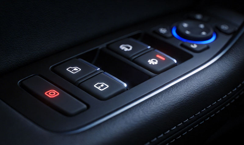
Automotive & POS Systems
For automotive dashboards or high-end POS terminals, we offer multi-color backlighting. Using precision multi-layer coating, we achieve localized lighting zones with different colors on a single keypad, enhancing both modern aesthetics and user-friendliness.
How Light, Legends and Key Feel Work Together
Illumination, surface artwork and the switch structure share the same limited space. A change made to improve one can affect the others, so these design decisions are reviewed together.
LED Placement and Light Uniformity
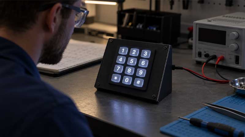
An LED creates a local source of light; the illuminated area is rarely identical to the LED footprint. If a source sits close to a clear legend, the center can look much brighter than its edges. If it sits too far away, a narrow symbol can appear weak. Silicone translucency, the distance to the source, nearby opaque areas and the housing cavity all affect the result. A light guide or diffuser can spread light, but it also changes stack height and the parts that must be supplied.
For example, a compact four-way navigation pad may have one LED near its center. That can suit a single illuminated ring, but four independently lit arrows need a different LED and masking layout. The decision should be made with the PCB and intended operating states, not from the rubber drawing alone. A powered sample in the intended housing is the practical way to judge hot spots, dark corners and light leakage between keys. SiTECH’s silicone keypad application guide also describes PCB LEDs, molded windows and light pipes as backlighting design options.
Legends, Finishes and Day-to-Night Readability
For a light-on-dark legend, a translucent silicone body may receive an opaque surface coating; laser removal then opens the symbol for light transmission. This is one possible construction, not a requirement for every illuminated keypad. Its value is the controlled lit area. Its limits include the size of fine artwork, registration between the legend and key, and how the coating behaves under repeated touching and cleaning. See laser-etched silicone keypads for the decoration process in more detail.
The key must also work when the LED is off. Dark-on-dark artwork that looks striking in a powered photo may be hard to find in daylight or during a power loss. Approve the appearance in both states, under the intended LED color and realistic viewing conditions. A color chip or loose keymat cannot show the same result as the assembled product.
Key Feel and Electrical Switching
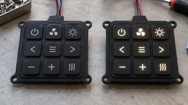
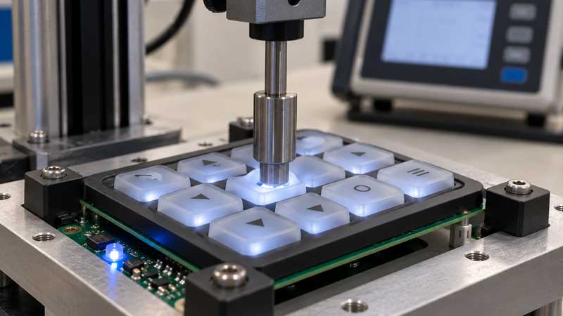
Backlighting should not displace the structure that makes the key work. Silicone web geometry, key height and material hardness influence actuation and return; the actuator or conductive contact must line up with the PCB switch pattern. The LED and its solder joints also need room outside the intended key movement. On a small keypad, changing the light source location may move the contact or alter the web; that can change feel even when the top artwork stays the same.
For a carbon-pill design, contact size and PCB geometry are part of the electrical specification. If the keypad presses a separate switch or metal dome, its travel and support are different. SKF’s conductive silicone keypad page addresses contact-focused designs. For this product, the decisive check is that the selected contact and lighting layout work together on the actual PCB.
From Drawing Review to Approved Sample
SKF’s silicone keypad prototype service covers functional samples with keypad geometry, legends, contacts and backlighting features. For a backlit project, development should begin by reviewing the keymat drawing with the PCB/LED arrangement and housing section. This identifies conflicts such as an LED occupying the contact area, a bezel shading an icon, or a thick light path that lifts the keypad out of position.
After the construction is selected, sample production can include molding, surface decoration and contact installation as required by the drawing. Laser etching follows the chosen coating and artwork route; it is not automatically a step for every design. The sample should be checked first as a part for dimensions and artwork, then in a powered assembly for visual appearance and switch operation. If the off-state contrast, key force or light distribution needs adjustment, the relevant artwork, material, PCB layout or tool feature can be revised before approval.
An approved sample establishes the agreed construction, powered appearance and key response. Recording these conditions allows later production parts to be checked against the same result if the artwork or another component changes.
A Backlit Keypad Built Around the Device
A successful backlit keypad is judged as part of the powered control interface: its legends must be readable, its keys must actuate as intended and the assembly must fit the device. SKF can help explore the appropriate construction and development path. Contact SKF to discuss your custom backlit silicone rubber keypad project.
Customization and Device Integration
These choices are considered together as the device design develops, rather than as independent cosmetic selections.
Design area | Options to specify | Why it affects the finished keypad |
Key layout | Count, pitch, shape, height, mounting edge and grouped force targets. | Controls finger access, housing fit and the space left for LEDs and contacts. |
Lighting | Lit legends or windows, LED color, separate zones and off-state appearance. | Determines translucent areas, masking and the powered assembly used for approval. |
Surface | Molded color or texture, printed details, opaque coating and an optional protective finish. | Changes daylight contrast, touch surface and the wear exposure to validate. |
Switch interface | Conductive pill, actuator for a separate switch, contact position and travel. | Determines how the keypad meets the PCB and whether the light path can share the available space. |
Fit, Materials and Supply Scope
The keypad outline, mounting lip and bezel opening establish mechanical fit. Lit legends, off-state visibility and independent zone states are settled as part of the interface design. Key groups can also have different force or travel requirements instead of assuming every key feels alike.
The supply boundary matters. Some projects use a decorated silicone keymat fitted over an existing PCB. Others include a light guide or an assembled subcomponent. The relevant assembly is used to approve appearance and function; a bright loose sample alone cannot show how the installed keypad will perform.
Material and finish selection follows the use conditions. Cleaning agents, finger oils, sunlight, temperature and expected press frequency can each affect the choice of coating and test plan. Silicone alone does not give a keypad an IP rating; a seal depends on the housing, compression, openings and final assembly. Medical or food-contact suitability likewise requires a specified material grade and supporting documents for the relevant use, rather than a blanket label on every product.
Backlit Silicone Keypad Design Options
Blue Arrow Backlit Silicone Keypad
Color-Coded 4x4 Backlit Silicone Keypad
Mini Backlit Silicone Keypad
Green Arrow Cross Backlit Silicone Keypad
Round Numeric Backlit Silicone Keypad
Single Power Button Backlit Silicone Keypad
Quality Checks for Backlit Silicone Keypads
Backlit parts need the ordinary checks of a molded keypad plus checks of the illuminated appearance. SKF lists dimensional, tactile, electrical and life-cycle methods in its keypad testing services; the applicable set is selected for the project.
For this product, an inspection plan can cover legend position and legibility, coating coverage, visible light leakage, relative brightness across keys, key-to-bezel clearance, force and travel, and contact response on the specified circuit. Visual checks should use the approved LED type, color and drive setting in a representative housing. Otherwise a change in the light source may be mistaken for a change in the rubber part. Where abrasion, cleaning, temperature or repeated operation matters, define the exposure and pass criteria against the intended application before testing.
Backlit Silicone Keypad Specification Reference
The values below give useful starting points for an OEM design. Common ranges are shown directly; where no single range fits all constructions, a documented design target gives a practical example to discuss.
Specification | General reference | Design consideration |
Layout and geometry | Custom to drawing | Key count, pitch, height, outline, mounting features and housing clearances. |
Silicone hardness | 40–70 Shore A | Common keypad material range; select the grade with web geometry and required feel. |
Actuation force | 80–500 gf | Common design range; key size, web geometry and measurement point affect the target. |
Key travel | 0.3–2.0 mm | Common design range; set the target with housing clearance and PCB/contact stack. |
Lighting | No universal numerical range | Lit areas, LED type/color, operating current or drive setting, viewing condition, acceptable uniformity and leakage. |
Legends and surface | Artwork and finish dependent | Source artwork, colors, lit and unlit contrast, coating/printing route and wear exposure. |
Carbon-pill contact resistance | Example target: <200 Ω | Applies only when a carbon-pill switch is used; PCB pattern, finish and test force affect the reading. |
Operating temperature | Example keypad range: −40 to +85°C | Check the completed design, including coatings, LEDs and electronics, against the required exposure. |
Key life | Example qualification target: 1 million actuations | Press profile, key geometry and acceptance criteria determine the project target. |
Ingress protection | Device-level rating | Housing, seal compression and assembly determine the final IP test result. |
The force, travel and hardness ranges are useful starting points; the temperature, life and contact figures show achievable design examples rather than fixed specifications for every keypad. If your project needs different values, SKF can discuss the construction and how to validate it in the intended assembly.
Why Work With SKF on This Project?
SKF’s published backlighting options, prototype service and testing services provide a path from the lighting concept to a functional sample and project-specific checks. That is useful when the buyer needs one review of artwork, rubber geometry and PCB interface instead of three unrelated component decisions. Supply scope, inspection and timing can then be discussed for the specific project.
Frequently Asked Questions
Are LEDs and the PCB included with the keypad?
The supply scope is project-specific. A backlit silicone keypad may be supplied as a decorated rubber keymat that fits an existing PCB, or as part of a wider assembly. The LED and PCB arrangement still influence the visible result, regardless of which parts SKF supplies.
Is laser etching required for every backlit legend?
No. Laser-opened artwork is useful for selected coated designs. Molded light windows and other material or decoration arrangements can also be evaluated. The choice depends on the lit area, daylight appearance, artwork size and intended wear conditions.
Can nearby keys light independently?
They can be designed as separate zones, but the result depends on LED position, opaque barriers, silicone transmission and housing details. Review all operating combinations on a powered sample; a single illuminated photograph cannot show cross-lighting between zones.
Can SKF work from an existing keypad sample?
A physical sample can establish shape, artwork and feel. SKF can discuss how closely those features can be matched; the result also depends on the existing lighting and housing arrangement.
Does a backlit silicone keypad have an IP rating?
An IP rating applies to the tested enclosure or assembly. The keypad may contribute to a seal, but the rating cannot be assigned from its material or appearance alone. Any ingress target has to be assessed in the complete device.
Can I discuss an early-stage concept with SKF?
Yes. An initial discussion can begin with the intended device, the functions that need illumination and the desired appearance. Detailed dimensions and technical targets can be worked through as the design develops.